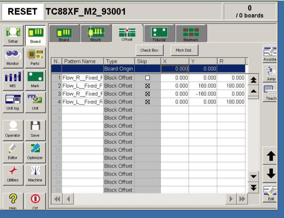
During the programming of the pick-and-place machine, the PCB coordinate file can be directly used for quick programming without individually locating the coordinates of each component. Once the PCB coordinate file is obtained, it means that the X and Y axis parameters of the pick-and-place processing file have already been determined; only the axis parameters of the pick-and-place file need to be confirmed. Familiarity with programming allows for faster product rollout, with the specific steps as follows:
Etapes de la programmation de la machine SMT pick and place
Export the “Generales pick and place files” from the PCB design software and copy it to the industrial computer of the pick-and-place machine.
In the “Import” tab, click “Open Import File,” select the file copied to the industrial computer, and click the “Open” button.

Once opened, retain only the Designator, MidX, MidY, and Solation, and rename these four fields in order as Position, X Coordinate, Y Coordinate, and Angle.
There are two methods to specify MARKI and MARK2: manual specification and system specification.
① Manual specification of MARK: In the PCB design software, remember the coordinates of the two diagonally opposite points, and fill the recorded pairs of coordinates into the MARK and MARK2 coordinates below, then click the “Generate” button. Move the MARK camera to find the MARK point and click the “Set MARKI Coordinate” button, then move the MARK camera to find the MARK2 point and click the “Generate MARK2 Coordinates” button.
② System specification of MARK: After selection, the system will automatically choose two MARK points from all coordinates, where MARKI is green and MARK2 is blue. Click the “Generate” button, then move the MARK camera to find the green bar point, click the “Set MARKI Coordinate” button, and again move the MARK camera to find the blue bar point, clicking the “Set MARK2 Coordinate” button.
After setting MARK2, it will automatically switch to the “Assembly” tab interface. Then specify the component position and nozzle number, right-click the mouse, and select the “Search Component Position” option, entering the position number of the components according to the exported BOM list.
After clicking the “OK” button, right-click on the appearing blue component → select “Associated Component” → choose the components corresponding to these placement positions, then right-click again → select “Nozzle Sorting” → select the nozzles needed for these components.
After all the settings are done, click the “Verify” button → then click the “Save” button.
Run.
Tag:SMT pick and place machine programming

