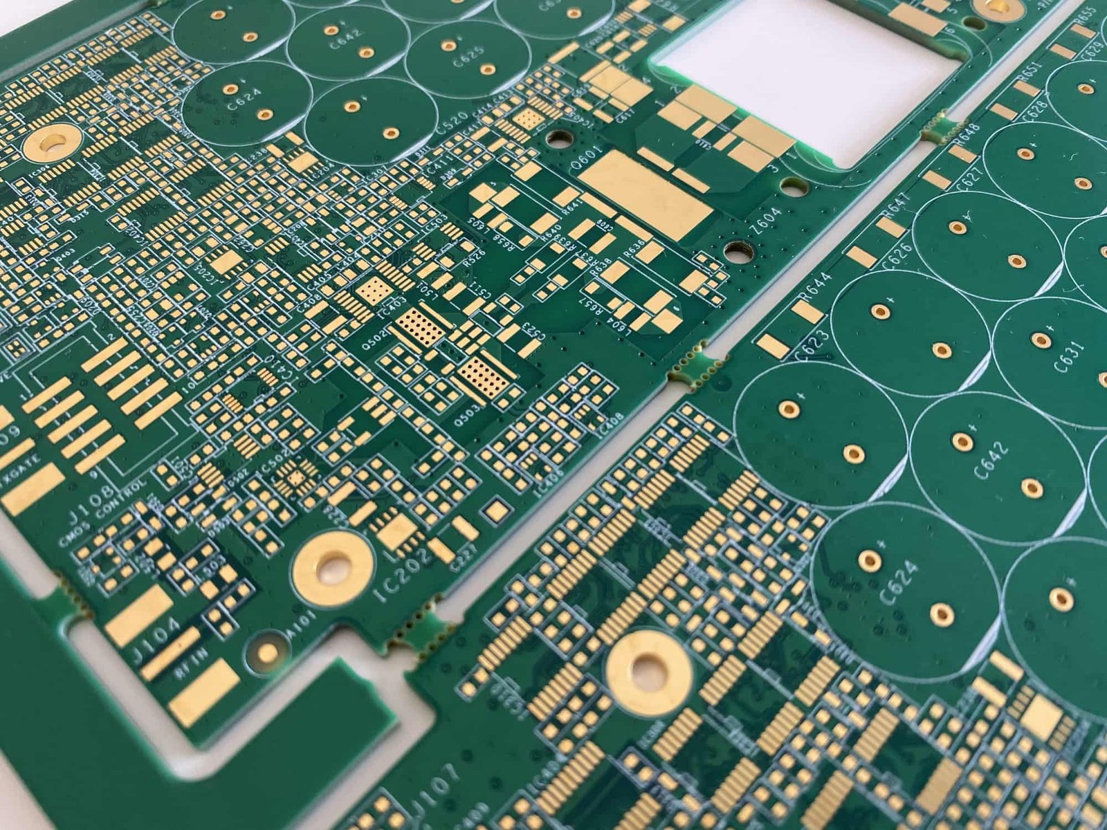
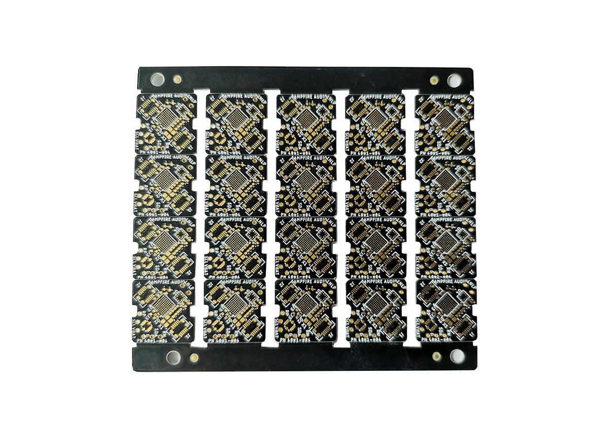
As the core carrier of electronic systems in the industrial control field, the reliability and stability of PCBs (Printed Circuit Boards) directly affect the performance of the entire device. Industrial control environments often face harsh conditions such as high temperature, high humidity, vibration, and electromagnetic interference, which demand higher design and manufacturing requirements for PCBs. This article delves into key technologies and methods to enhance the reliability and stability of industrial control PCBs.
1. Material Selection: The Foundation of Reliability
The choice of materials for industrial control PCBs directly impacts their long-term stability. Unlike general consumer electronics, industrial control PCBs require high-performance substrates:
- Substrate Materials: FR-4 is a common choice, but for high-temperature environments, high Tg (glass transition temperature) materials such as FR-4 High Tg (above 170°C) or Polyimide (PI) should be considered, as these materials maintain stable mechanical and electrical properties at high temperatures.
- Copper Foil Thickness: Industrial control PCBs typically require thicker copper foils (2 oz or more) to enhance current carrying capacity and heat dissipation, particularly in high-power applications.
- Solder Mask Ink: Select high-quality solder mask inks with good chemical resistance, high-temperature resistance, and insulation properties to prevent performance degradation caused by environmental factors.

2. Design Optimization: The Core of Stability
Reasonable PCB design is crucial to ensuring reliability:
- Thermal Management Design: Properly layout heat-generating components, use thermal vias for heat dissipation, and add heatsinks or consider metallic substrates (such as aluminum substrates) as necessary.
- Power Integrity: Use star or mesh power distribution networks to ensure stable power supply; increase decoupling capacitance to reduce power noise; power layers and ground layers should be adjacent to form good capacitive coupling.
- Signal Integrity: Control trace impedance matching to reduce signal reflection; use differential pair design for high-speed signal lines; keep critical signal traces away from noise sources and power lines.
- EMC Design: Properly layout ground planes to minimize ground loops; isolate sensitive circuits from noise sources; add shielding measures as necessary.
3. Manufacturing Processes: Means of Achieving Reliability
High-quality manufacturing processes are vital for PCB reliability:
- Surface Treatment: Choose an appropriate surface treatment process based on the application environment. Industrial control PCBs often use ENIG (Electroless Nickel Immersion Gold) or immersion tin processes, which offer good solderability and oxidation resistance; in extreme environments, consider using gold plating or OSP (Organic Solderability Preservative) processes.
- Hole Wall Quality: Ensure that the walls of through holes and blind/buried holes are smooth and evenly plated to avoid reliability issues caused by wall separation or uneven plating.
- Solder Mask Process: The solder mask should completely cover non-soldering areas, with clear, burr-free edges and uniform thickness to prevent short circuits and corrosion.
- Quality Control: Strictly follow standards such as IPC-A-600 and conduct comprehensive electrical testing, impedance testing, and reliability testing of PCBs.

4. Environmental Adaptability Design
PCB design must consider the specific requirements of the industrial control environment:
- Damp Proofing: Use high TG materials or add moisture-proof coatings to prevent moisture penetration that could lead to performance degradation.
- Shock Resistance Design: Increase board thickness (e.g., 2.0mm or more), optimize component layout to reduce cantilever structures; apply underfill to strengthen critical components.
- Corrosion Resistance Design: In corrosive environments, consider using special coatings or sealing processes to protect PCBs.
- Wide Temperature Design: Choose wide-temperature components and materials to ensure normal operation under extreme temperatures.
5. Testing and Validation
Comprehensive testing is the last line of defense for ensuring PCB reliability:
- Environmental Stress Testing: Includes temperature cycling, high temperature and humidity tests, vibration tests, etc., to simulate actual working conditions.
- Accelerated Aging Testing: By increasing stress levels, rapidly evaluate the long-term reliability of PCBs.
- HALT (Highly Accelerated Life Testing): Gradually increase stress to identify design limits and potential defects in the product.
- Field Testing: Conduct long-term operational testing in actual working environments to validate the stability of PCBs.
6. Maintenance and Monitoring
Even after PCBs are put into use, further measures are needed to ensure their long-term reliability:
- Status Monitoring: Utilize sensors to monitor critical parameters such as temperature, humidity, vibration, etc., to promptly detect potential issues.
- Preventive Maintenance: Regularly check PCB status, clean dust, and inspect connector contact conditions.
- Failure Analysis: Conduct detailed analysis of failed PCBs to identify root causes and provide feedback to design and manufacturing processes.
For those aiming to boost the reliability and stability of PCB production, I highly recommend checking out the equipment at Winsmt. Their advanced SMT solutions, including precise placement machines and efficient reflow ovens, are designed specifically for industrial control applications. These devices ensure high-quality manufacturing, excellent thermal management, and thorough automated testing, helping you achieve superior performance under demanding conditions. Explore Winsmt’s product page to elevate your PCB manufacturing process!

