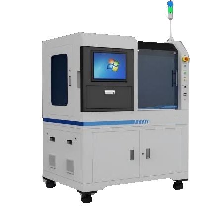
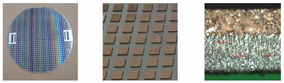
Equipment processing size: suitable for 4- inch to 6- inch wafer processing work. Equipment appearance: See the picture on the right.
Supporting special equipment: SIC laser cutting equipment
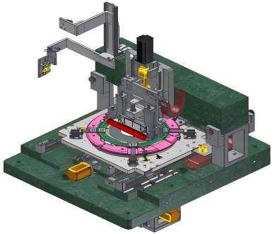
Automatic loading and unloading structure Vision Positioning System Stage splitting system Electrical control system Core components are all marble structure
The splitting process is to apply a certain amount of slight pressure along the laser scratch path to the product to break the laser scratch. Process: The product is placed on a symmetrical support table (the middle distance is adjustable ) , calibrate the laser cutting position through a high-precision visual system Positioning (micrometer level positioning ) The split knife (blade width 5 um ) above the product is quickly raised and lowered to make the product move along the cutting path . (Laser scratch) Crack and separate .
This technology has been maturely applied to various SIC , silicon wafers, sapphire, and various mixed brittle material fragments, The yield rate in traditional industries is generally above 99%. It has high positioning accuracy, effectively reduces edge collapse, and solves the problem of incomplete twin crystal fracture. The technological advantages of the surface.
Silicon carbide processing solution: chip facing up, blade cutting path:
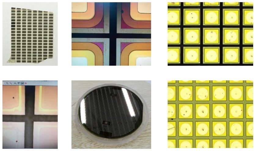
Primarily used for cutting LED red and yellow light silicon wafer chips, as well as for cutting special materials such as ceramics and metals.
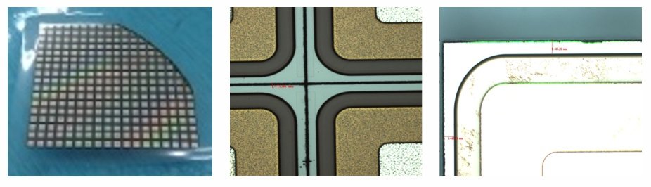
The crack length is calculated based on the wide-angle profile, and the cutting depth is compensated according to the value in the length compensation table when splitting . Hammer Percent sets the hammer force compensation.
To solve the focus change caused by the edge warping of LED wafer products during the chipping operation, the software can Set the autofocus area to automatically confirm the focus, ensure the accuracy of the fragmentation, and reduce the calibration level alarm caused by focus changes.
The riving knife can be replaced conveniently by operating the button of the tool loading software ; The automatic tool setting function automatically corrects the position of the riving knife, automatically checks and corrects during operation, and avoids core hardware errors. Product anomalies;
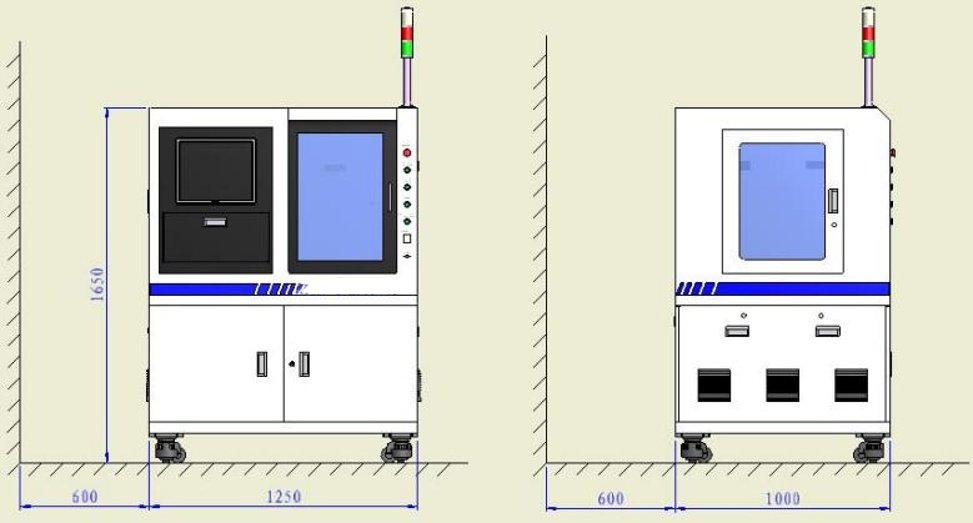
(W)1250 × (D)1000 × (H) 1650 ( mm ) (excluding signal lights) In addition , at least 600 mm
Electricity Demand | 220V/ Single Phase /50Hz/ 10A |
Ambient Temperature | 20-25℃ |
Environment Humidity | 20%-60% |
Compressed Air | 0.6MPa |
Compressed Air Connection | Φ8mm |
Environmental Vibration Requirements | Foundation Amplitude < 5μm Vibration Acceleration < 0.05G |
Equipment installation and commissioning, training plan | ||
Working Days | Job Description | Remark |
Day 1 | 1. Machine installation and placement 2. Machine base level adjustment 3. Machine interior 4. Power on and ventilate the equipment 5. Power on all components of the equipment check 6. Platform accuracy test | |
Day 2 | 1. Confirmation of the splinter effect 2. Splinter test according to customer’s on-site requirements | |
Days 3-7 | 1. Split test according to customer’s on-site requirements 2. Training: Equipment safety training 3. Training: Introduction to the structure and function of the whole machine 4. Training: Operator Basic operation introduction 5. Training: Operator trial operation 6. Training: Training for administrators on software file creation, parameter settings, etc. 7. Training: Training on handling common problems for administrators 8. Training: Management Simple maintenance training for staff and equipment | Training work based on Customer’s personnel security Row, and training Content mastery Degree, training work According to customer requirements Request for continuation |
Day 8 and beyond | Cooperate with customers to carry out various dicing process tests and equipment acceptance work |
Rm3A08 (4th Floor) Block D, Huashengtai Technology Park, No.36 Hangkong Road, Baoan District, Shenzhen City, China
© 2025 All Rights Reserved.